Courage the BioBot Lunar Surface Rover

Acknowledgements
I thank my team members Justin Albrecht, Sayani Roy and Brian Patrick Bock who worked with me to design the BioBot lunar surface rover and without their help, ideas and innovation this project wouldn’t have been possible.
I would also like to thank my professor for this course Dr. David Akin for his invaluable support and guidance throughout the project.
Introduction & Project Description
A BioBot rover is a semi-autonomous vehicle which is capable to carry and function as a life supports system for the EVA crew, while simultaneously also being capable of seating and carrying the astronauts (EVA crew).
In this project we performed a detailed design of a BioBot rover, emphasizing mobility systems, chassis systems (e.g., wheels, steering, suspension, etc), support systems (e.g., energy storage, etc), navigation and guidance system (e.g., sensors, algorithms, etc). The system must be designed for the Moon, then evaluated for Mars and conversion into an Earth analog rover.
Problem Statement
While designing the rover we were tasked to fulfill some requirements which are given below:
-
The rover must be capable of achieving a maximum operating speed of at least 4 m/sec on level, flat terrain.
-
It must be able to accommodate a 0.3 m obstacle at minimal velocity, a 0.1 m obstacle at a velocity of 2.5 m/sec, and/or a 20° slope in any direction at a speed of at least 1 m/sec, including the ability to start and stop as required.
-
A nominal sortie has a range of 54 km at an average speed of 2.5 m/sec.
-
Payload: The rover must be capable of carrying one 170 kg EVA crew and 80 kg of assorted payload (modeled as a 0.25 m box).
-
The rover must also be capable of carrying a second 170 kg EVA crew in a contingency situation.
-
The design should incorporate roll-over protection for the crew and all required ingress/egress aids and crew restraints.
-
Operations: A nominal sortie shall be at least eight hours long.
-
Two rovers must be launched on a single CLPS lander; A single rover shall have a mass ≤250 kg.
-
The rover(s) must be capable of operating indefinitely without a crew and it must be capable of being controlled directly, remotely, or operate autonomously.
-
It must be capable of following an astronaut, astronaut’s path, or autonomous path planning between waypoints, and capable of operating during any portion of the lunar day/night cycle and at any latitude.
Rover Design
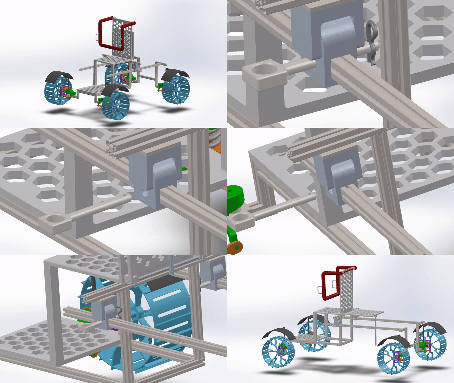
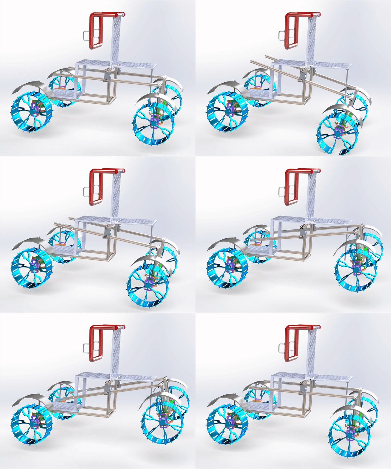
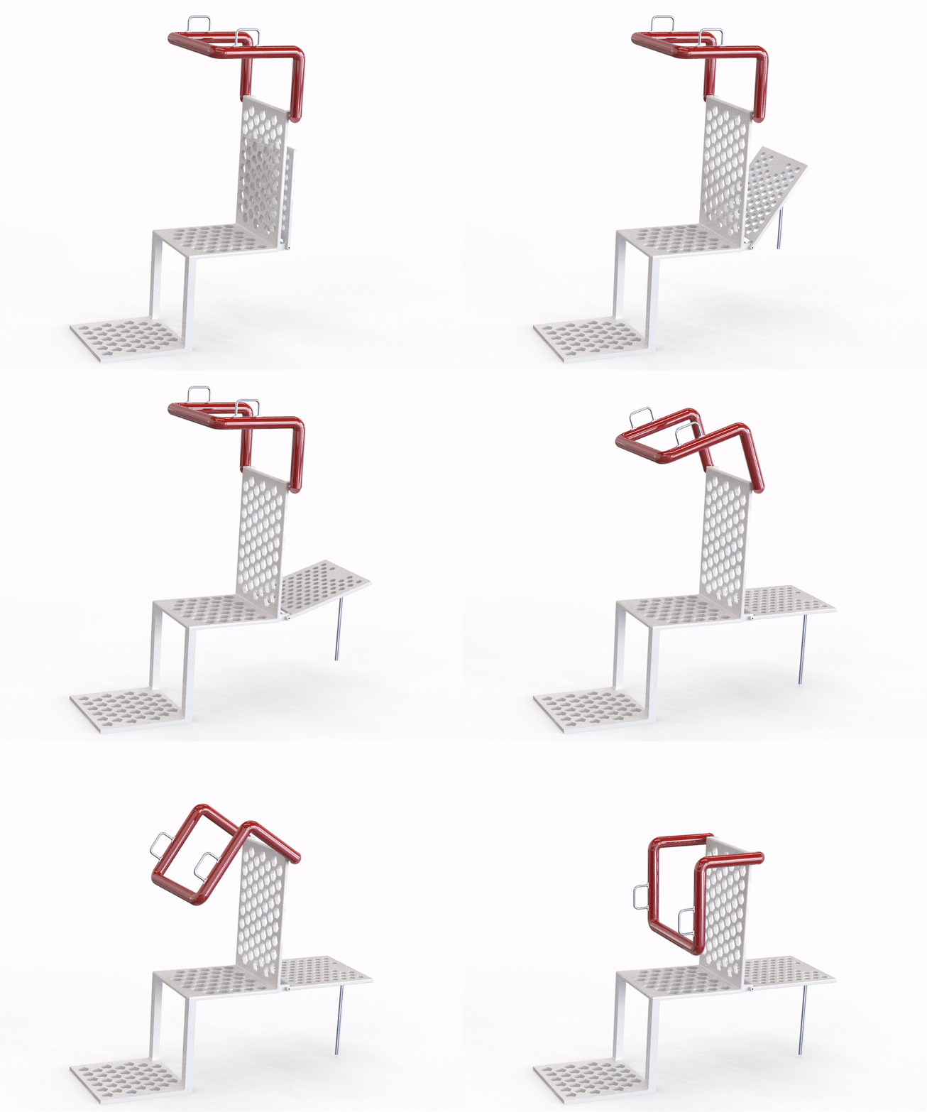
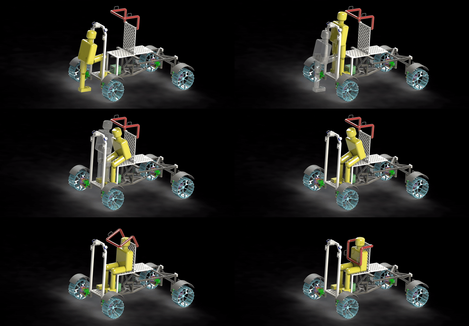
As can be seen in the images above the rover courage is designed for two states first being the non-extended version which is able to seat one EVA crew and the second being the extended version which is able to carry two EVA crew members during emergencies. The states can be morphed from one to another with the help of a pivot, rack and pinion mechanism. The extended mechanism is introduced rather than having a fixed chassis so that the overall stability of the rover is maintained. These assumptions will be verified later on in the project below.
Terramechanics
Drawbar Pull
Here Drawbar pull is a function of velocity and it decreases as the acceleration increases. We use drawbar pull to determine the dimensions of our wheels.
From the graphs above and comparisons made from the calculations done in MATLAB, a rover with 4 wheels is selected from a choice betweenf 4 and 6 wheels.
The design parameters of the wheels are as follows:
-
Number of wheels (N) = 4
-
Diameter of wheel (d) = 0.6m
-
Width of wheel (w) = 0.3m
-
Number of grousers = 20
-
Height of grousers = 2 cm
Stability
For our selected rover with 4 wheels, we find its stability on both flat terrain and a slope of 20 ° in both cases: Non-Extended and Extended.
Steering
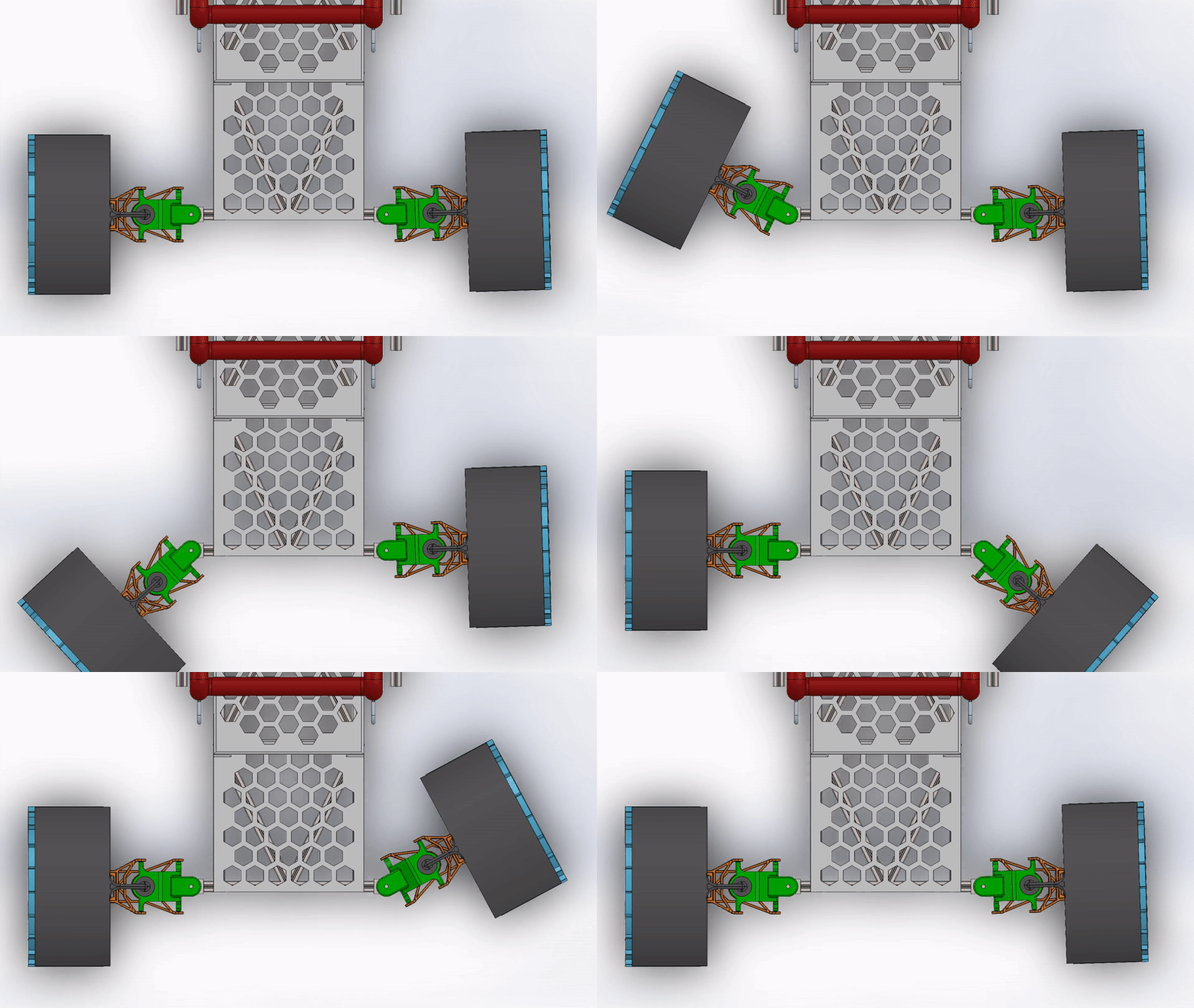
The front two wheels operate on a direct steer, each with a steering motor. Both the rear wheels wheels are fixed to the chassis.
Suspension
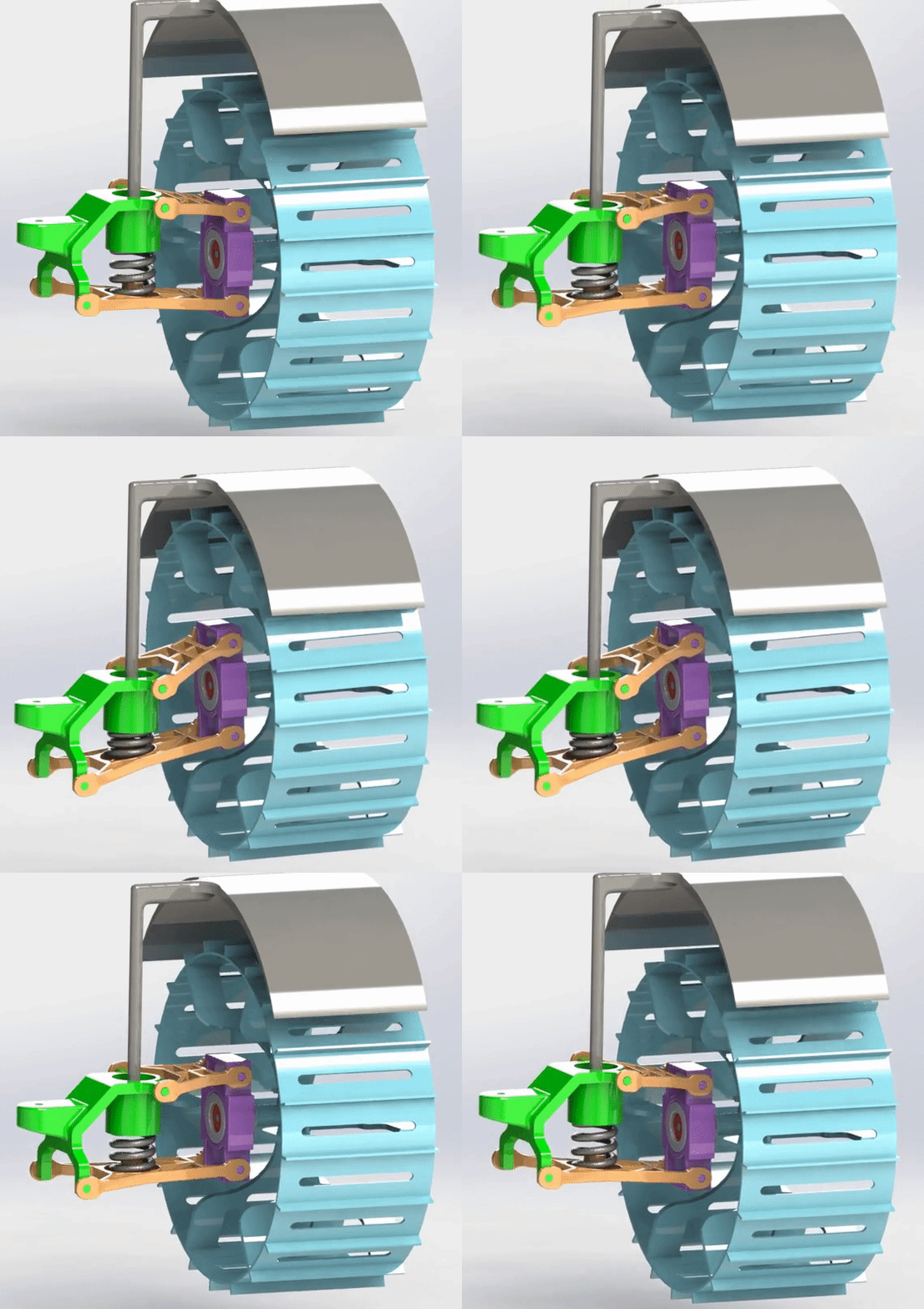
The suspension system we have chosen is known as a double-wishbone suspension. This type of suspension is often used in commercial vehicles. The system has a main bracket that connects either to the steering motors in the case of the front wheels or directly to the chassis for the rear wheels. From this bracket there is a top wishbone and bottom wishbone each mounted on pivots. A spring lies between the wishbones that returns the system back to a neutral position. The other two ends of the wishbone connect to our drive motor bracket which it turn connects to the wheel.
The main benefit of this type of suspension is that there is very little wheel camber relative to wheel motion. In other words the wheel should stay mostly perpendicular to the chassis throughout the range of motion.
Independent Suspension Calculations
Following the steps for independent suspension calculations, we can determine the force on each of the wheels. The error for the three constrain equations below are minimized to find the roll, pitch, and z offset of the rover. These constraint equations ensure that the error for the sum of the forces and moments are close to zero. These values can be applied to our rover transforms to find the height of each wheel offset from the base frame of the rover. For our calculations, we set the COM offsets for both the standard configuration and the extended configuration.
The results on flat ground in both the extended and standard case are shown below:
Motors
There are two types of motors required for this rover design - steering motors and driving motors. Motors to be used were chosen depending upon the requirements of the steering motor and driving motor.
Steering Motor Requirements
Using the turning radius value for non-extended and extended configuration, the power required to steer the rover was calculated.
The figure below shows that the rover requires a steering motor with an output power of 160 Watts to steer the rover either in a non-extended or extended configuration.
Motor Selection
Brushless DC motors were chosen as they require low maintenance and have a long lifespan as well as high efficiency. A motor from RBE(H) 01212 series was chosen for both driving and steering motor as it satisfies all the power, torque and speed requirements.
Sensors, Perception, and Computing
The rover needs to be operable autonomously, so it needs sufficient proprioceptive and exteroceptive sensors and computational power to understand it’s environment.
Lighting
Without an atmosphere to reflect ambient light, the lunar surface is dark and shadowy. Proper illumination will be important for the astronauts to work and for the rover’s vision systems to function in a useful way. We’ have equipped the rover with four 35,000 lumen LED floodlights for illumination. LED floodlights have terrific energy efficiency (especially when compared to incandescent or halogen) and provide excellent brightness for very little weight. By far, most of the weight of the floodlight assembly is the plastic/glass/metal housing, and the LEDs themselves contribute negligibly.
LIDAR
The rover will be equipped with 4 Velodyne Puck LITEs for complete LiDAR coverage. The Puck LITE was chosen (instead of the Ultra Puck or Alpha Puck) for its lower weight. The rover is a singular vehicle on the moon (as compared to hundreds of vehicles in the immediate vicinity of a car on an Earth highway) and therefore doesn’t need the superior response time or resolution of these higher-end pucks. The Puck LITE still provides an impressive 100m range, 30° vertical field of view, and 3cm accuracy.
Cameras
A comprehensive vision system will be valuable for autonomous rover operation, as well as more detailed science (especially science/operation conducted remotely from Earth). Camera quality has improved dramatically since the 1960s, and we can now supplement our rover with a number of very high-quality cameras that require mnimal financial, power, or weight costs. We’ve selected 7 Earth-analog cameras which (when modified for a space environment) would be excellent for the rover system. We start with two Sony 4K BRC-x400 Pan Tilt Zoom (PTZ) cameras, each weighing 1.8kg and requiring 25W (max). The 3 degrees of freedom in these cameras make them very useful for exploring an environment. Stereo cameras, in which two cameras side by side can provide binocular depth perception, are useful for both visual perception and depth. These supplement the Velodyne LiDAR pucks’ ability to understand the geometry of the nearby environment, adding both additional information and failure-proofing redundancy into the system. Intel makes several stereo vision cameras, including the RealSense D455, which boasts a depth range from 0.4m to 20m. The cameras listed above have a restricted range of view and can only perceive objects in one direction. While there may be some overlap in their potential coverage, it will also be helpful to have a camera with an unobscured 360° view of the surroundings. The GoPro Max is incredibly compact, lightweight, and offers 6K video recording capabilities of the entire environment via two opposing wide-angle cameras. The addition of this (or a comparable) camera ensures that the rover will have no blind spots and will be able to operate completely autonomously. This camera may also be useful for remote operation and remote troubleshooting. To enable the rover to track the astronaut, each astronaut’s EVA suit would be augmented with retroreflectors and fiducial markers (like April tags), which would be clearly visible to the cameras. Additional tracking features like ultra wideband triangulation or motion capture bulbs may also be implemented.
Motion Sensors
The rover will have encoders on each wheel as well as several multi-axis inertial measurement units (IMUs) on board to fully understand its pose and how it has traveled. These will serve in feedback loops for the driving controllers to help ensure the rover drives to exactly where it is intended to go. The exact details of these sensing systems depend tremendously on the detailed specifications of the entire rover as well as the control schema, the latter of which is out of scope for this project.
Computing
Autonomous path planning and full utilization of LiDAR + cameras require non-trivial computing power, certainly more than we have sent to the Moon (or Mars) previously. Modern laptops are fairly capable, and it’s possible that a very high-end laptop would have sufficient computational power (and speed) to be useful in this scenario. In a slightly larger (and much more power-hungry) form factor, a gaming desktop computer with a dedicated GPU, more RAM, and 8+ CPUs is certainly a capable solution for this task. The winning trade-off between electrical power and computational capability would depend on the available power, weight, and needs of the system. We assumed that a high-end laptop (minus the screen) would be viable for this project (1kg, 61W).
Communication
The idea of several 8-hour sorties implies that there will be an established habitat (“Hab”) on the moon prior to the arrival of the rover or astronauts. We assume the Hab is well equipped with sufficient radio equipment to communicate with Earth at an excellent speed duplex. The rover only needs to be capable of communicating with the Hab, which would then relay any Earth-bound communications in that direction. The rover has a specified driving range of 54km. Assuming the astronauts have to be in the Hab at the end of the sortie, the furthest they can drive is 27km (half of 54km out, and the other half back). Modern smartphones communicate wirelessly over a range of cellular data protocols, most of which are fairly long-range and high bandwidth. The smartphone requires very little mass or power to engage in these communications. It’s not hard to imagine that a Hab equipped with comparable cell tower technology could communicate with the rover in a similar way and that the requisite communication apparatus in the rover would be negligibly small in mass and power. We’ll roll these communication mechanisms into the on-board computer.
Mass and Power
The Hab must be equipped with its own power supply (nuclear or solar, likely). The rover only needs to carry enough power for an 8 hour day of use and can be recharged overnight by the Hab.
Final Design


Non-Extended Version
Extended Version


Flat Terrain
20 degrees Slope





Standard Configuration
Extended Configuration


